
Hello Friends.
Today will have some discussion on installation of cables.
Basically in my earlier post i have mentioned something about types of cables.
Different types of cables are as follows:
1. Armoured Cable
2. Unarmoured cable(Flexible cable)
Again in above two we also have something called FRLS(Fire retardant Low Smoke) which is generally used in hazardous area. So we call it as FRLS Cable.
Now would like to discuss here about different steps involved in installation of cables as follows:
1.Laying of cables
2.Glanding of cables
3.Lugging of cables
4. Testing of cables
5.Termination of cables
First of all we do laying of cables it could be above ground or underground or piperack.
While cable laying is being done it should be ensure to do its dressing at a distance of every 1metre by cable tie or aluminium clamps. Upto possible extends overlapping of cables should be avoided .
Also need to ensure sufficient distance between Instrument/Communication and Power Cable should be atleast 300mm in order to avoid its interferences.
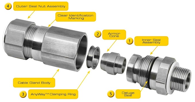
Once cable laying is done we have to do glanding of cables in order to enter into panels.
Photo of Cable gland is as shown below:

Cable glands are defined as ‘mechanical cable entry devices’ which are used in conjunction with cable and wiring for electrical, instrumentation & control, and automation systems, including lighting, power, data and telecoms.
The main functions of the Cable Gland are to act as a sealing and terminating device to ensure the protection of electrical equipment.
After doing this cable glanding works , all the cores of cables are exposed in order to do lugging of cables.
Photo of Lugs used for cable is as shown below:

This Lugging means connecting of cable core to device called Lugs in order to connect it to terminals inside panel or any equipments.
The above process is called of Lugging of cables.
After completion of lugging of cables it is being tested by High voltage test.In this test cables are open from both the ends of and from one end High voltage of 1.1KV is applied for 1minute and insulation resistance is measured. It shuold come in Mega Ohms and ideally it should be greater than 10Mega ohms for cable rated of 1.1Kv.
This value shows the healthiness of cables if it is found satisfactoty, then we can go ahead for the final step of cables installation which is termination of cables.
Final step is termination of cables which basically nothing but doing connection to point where it has to provide power supply.It could be inside panel, equipment like motor of any other bus-bar junction.
Photo of termination of cable as shown :

Above photo it is shown cable is connected to switchgear called MCCB.
R,Y,B are the color codes of cable while black is neutral one.
So finally once termination is done we can say now the cable installation work is completed and power can be transmitted or supplied through this cable.


1 Comments
The types of cables, allowed in cable trays, and the wiring methods permitted in cable trays can be found in NEC Section 392.10 (A). This Section also lists various corresponding NEC Articles which describe the conditions of use and installation requirements for a particular class or type of cable. Additional considerations such as fill capacity, allowable ampacity, cable splicing within trays, and securing and supporting cables are addressed in Article 392. Users should be familiar with all these Articles and check the manufacturer’s specifications, to verify selected cables meet all application requirements and NEC requirements.
ReplyDeleteCable Tray